DigSim
DigSim is an interactive digital logic simulator written in Python.
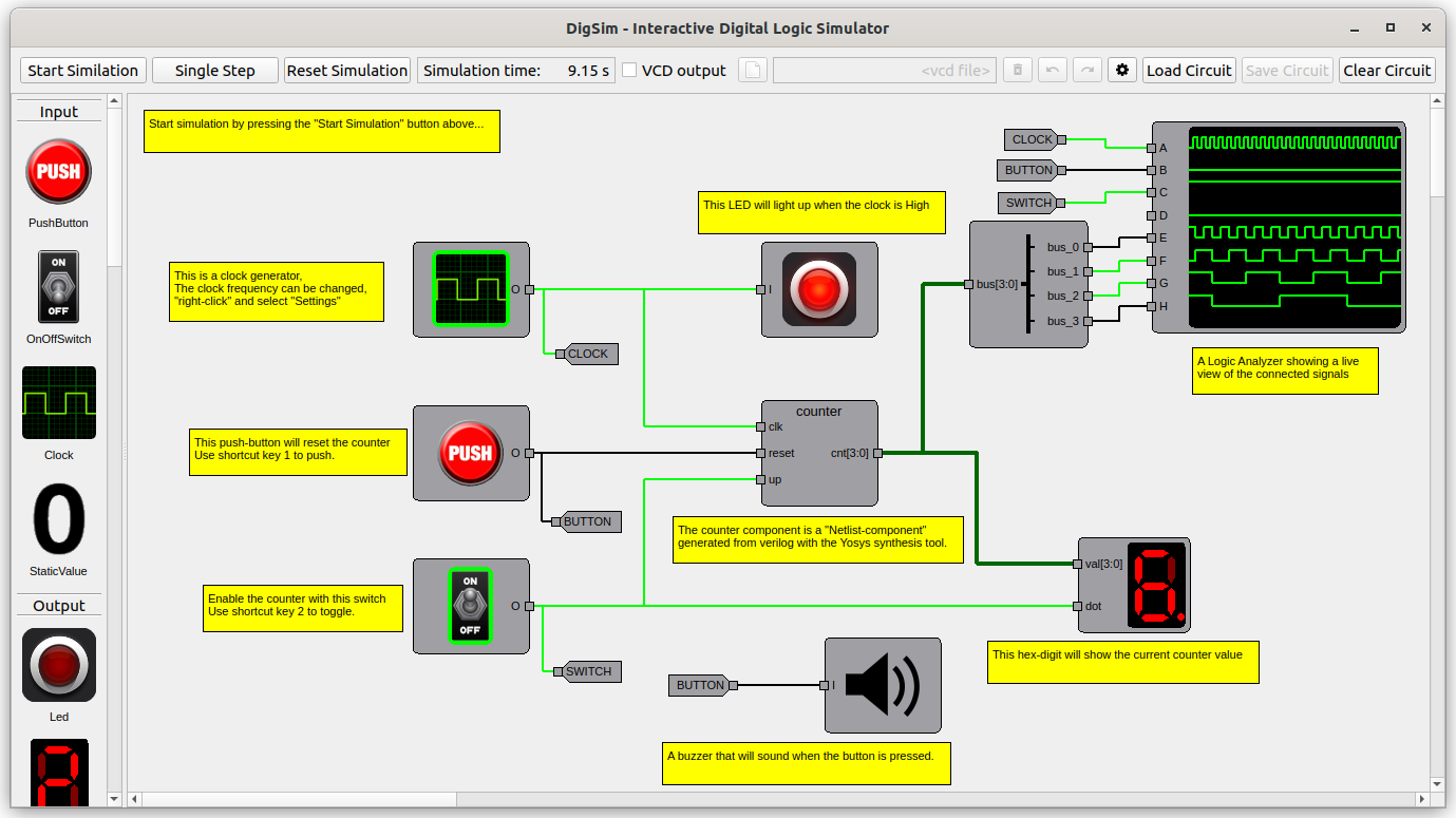
It is made for learning and experimenting with digital logic, from single gates to complete Verilog designs. Build a circuit by dragging components onto a canvas, start the simulation, and press buttons, flip switches and watch LEDs and hex displays react in real time.
Why DigSim?
Simulating a Verilog or VHDL design normally means writing test stimuli and reading waveforms afterwards, which is not a very interactive way of working. Testing the design on an FPGA gives you real buttons and LEDs, but synthesis and programming take time (and sometimes money), so every change has a long turnaround.
DigSim sits in between. You can load a Verilog module straight into the simulator, wire it to buttons, switches and displays, and play with it immediately. Edit the Verilog, reload the component, and try again.
DigSim started as a way to visualize simple Verilog modules. It has since been used to simulate larger designs, such as the classic 6502 CPU. It is slower than dedicated simulators, but fast enough to be useful.
Features
- Interactive GUI: build and simulate circuits with buttons, switches, clocks, LEDs, LED bars, hex digits, 7-segment displays, a buzzer and a logic analyzer.
- Python API: create and simulate circuits in plain Python code, for scripts or pytest testbenches.
- Verilog support: turn Verilog into simulatable components using a bundled WebAssembly build of Yosys. No separate install needed.
- Waveforms: write simulation results to VCD files and inspect them in GTKWave or a similar viewer.
Get started
- Install DigSim, or run it directly with
uvx digsim-logic-simulator. - Learn the GUI application.
- Script circuits and testbenches with the Python API.
- Bring your own Verilog designs.
- Try the examples.
- Create your own components, and contribute them.
DigSim is open source and developed on GitHub. Bug reports and ideas are welcome as issues.