GUI Application
The DigSim application is a circuit editor and simulator in one window. You place components, connect them with wires, and start the simulation to interact with the circuit live.
Start it with digsim-logic-simulator (or python -m digsim.app). See
Installation for all ways to install and run it. To open a saved
circuit right away, pass it with --load:
digsim-logic-simulator --load example_circuits/counter_yosys_netlist.circuit
The example_circuits
folder in the repository has ready-made circuits to explore.
The main window
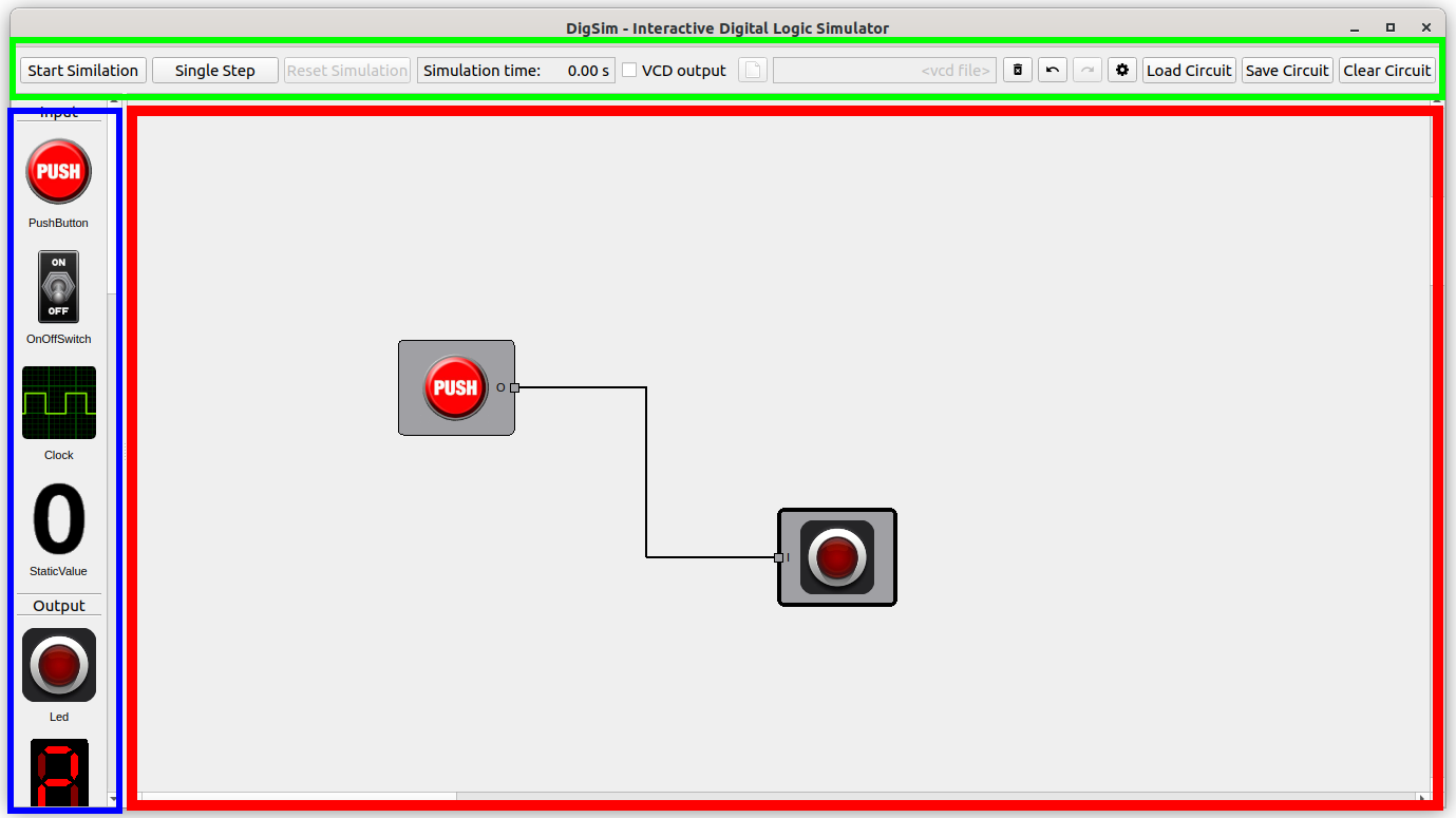
The window has three areas:
- Component selection (blue, left): all available components, grouped by type.
- Circuit area (red, right): the canvas where you build the circuit.
- Control area (green, top): simulation controls, VCD output, and buttons for loading, saving and clearing circuits, plus Delete, Undo, Redo and Settings.
A typical circuit consists of:
- one or more input components such as buttons, switches or clocks,
- some logic, for example gates, flip-flops or more complex components,
- one or more output components such as LEDs or hex digits.
Working with components
Add a component by double-clicking it in the component selection, or by dragging it into the circuit area. While you drag, a see-through preview shows where the component will be placed: centered under the mouse pointer. Components with options open a settings dialog when they are added.
Right-click a component to open its context menu:
| Menu item | Action |
|---|---|
| Bring to front / Send to back | Change the drawing order of overlapping components |
| Delete | Remove the component and its wires |
| Settings | Change the component's options (only for configurable components) |
| Shortcut | Assign a keyboard shortcut (push buttons and switches) |
| Reload | Reload the Verilog file or netlist (Yosys components) |
Click a component to select it, and drag it to move it. Delete the selected component with the Del key or the Delete button in the control area.
Wires
Wires connect component ports. To draw a wire, click a port, then click the port you want to connect it to. Press Esc to cancel a wire you have started.
- One output port can drive any number of input ports.
- Both ends must be of the same kind: a single-bit wire, or a bus of the same width. Use the bus/wire converters to split or merge buses.
- Wire Source and Wire Sink components connect signals by label instead of with a drawn wire, which keeps large circuits readable.
Simulation
Once the circuit has inputs and outputs, it can be simulated.
| Control | Action |
|---|---|
| Start Simulation / Stop Simulation (or Space) | Run or pause the simulation |
| Single Step | Run until the next input event, such as a clock edge |
| Reset Simulation | Restart the simulation from time zero |
While the simulation runs:
- click a push button to press it, and click a switch to toggle it,
- use keyboard shortcuts to operate buttons and switches,
- the current simulation time is shown in the control area.
The circuit cannot be edited while the simulation is running.
Application settings
The Settings button in the control area opens the application settings:
| Setting | Description |
|---|---|
| GUI Update Frequency | How often the display is refreshed (1–100 Hz) |
| Slow down sim to 'Real Time' | Keep simulation time in step with wall-clock time |
| Show Wire Value | Color wires by their current logic level |
VCD output
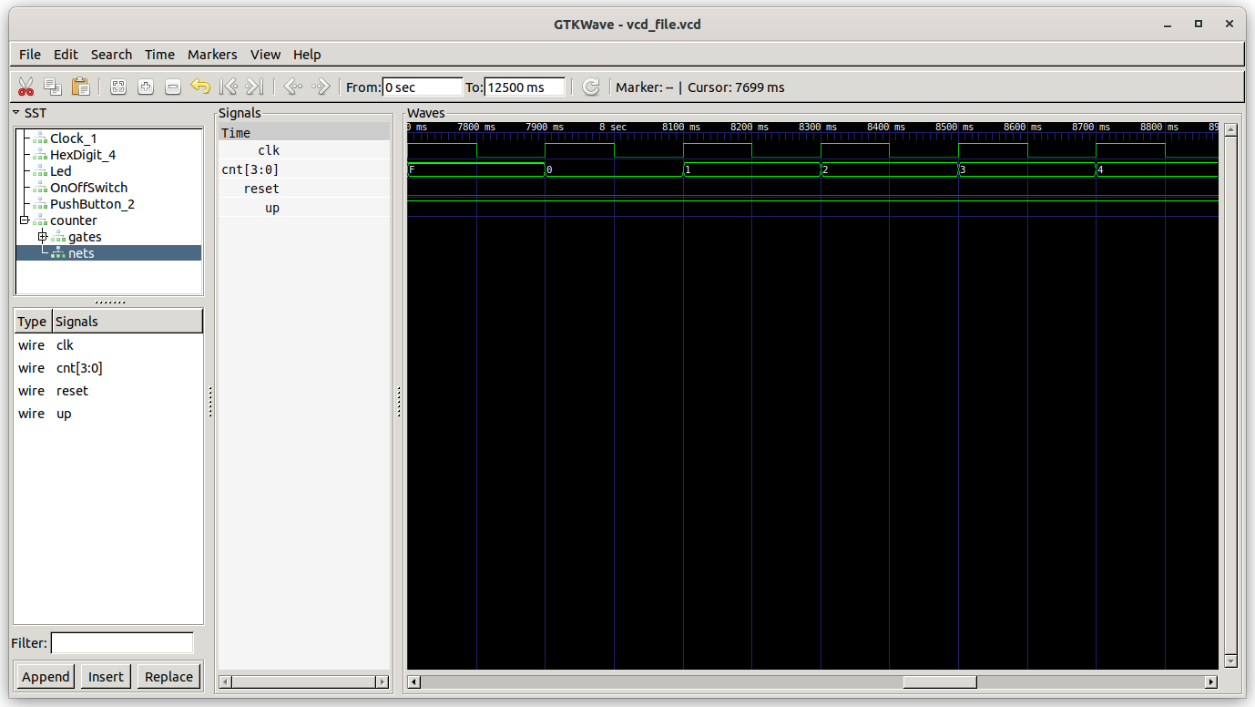
Check VCD output in the control area to record all signals to a VCD file while simulating. Open the file in GTKWave or a similar waveform viewer.
Navigation and keyboard
| Key / mouse | Action |
|---|---|
| Ctrl + mouse wheel | Zoom in and out around the mouse pointer |
| Ctrl + + / Ctrl + - | Zoom in / out |
| Shift + drag | Pan the circuit area |
| Ctrl + Z / Ctrl + Y | Undo / redo |
| Del | Delete the selected component |
| Space | Start / stop the simulation |
| Esc | Cancel the wire being drawn |
Keyboard shortcuts for inputs
Push buttons and on/off switches can be bound to the keys 0–9. Right-click the component, choose Shortcut, and pick a number. While the simulation runs, the key presses the button or toggles the switch.
Component reference
Input components
| Component | Description |
|---|---|
 |
Push Button: outputs a high level while it is pressed. |
 |
On/Off Switch: toggles its output each time it is clicked. |
 |
DIP Switch: a row of switches, one output per switch. |
 |
Clock: a square wave with a configurable frequency (1–50 Hz). |
 |
Static Value: a constant value on a wire or a bus (1–16 bits). |
Output components
| Component | Description |
|---|---|
 |
LED: lights up when driven by a logic high. |
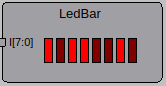 |
LED Bar: a row of 1–16 LEDs showing the bits of a bus, the most significant bit to the left. |
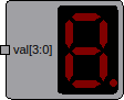 |
Hex Digit: shows a bus value in hexadecimal, with 1–8 digits (4 bits each) and an optional decimal point. |
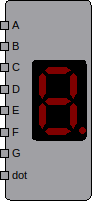 |
7-Segment Display: like a hex digit, but each segment is controlled individually. |
 |
Buzzer: plays a tone, with a selectable note, when its input is high. |
 |
Logic Analyzer: plots signal levels over time, live. |
Logic gates


OR, AND, NOT, XOR, XNOR, NAND and NOR. All gates except NOT can be configured with 2 to 8 inputs. With more than two inputs, XOR is high when an odd number of inputs are high, and XNOR when an even number are.
Flip-flops
| Component | Description |
|---|---|
 |
D Flip-Flop: 1–32 bits wide, with optional clock enable and asynchronous reset. |
 |
Flip Flop: choose an SR flip-flop, or an edge-triggered SR, JK or T flip-flop. |
Multiplexer

The multiplexer has 2, 4 or 8 inputs and a data width between 1 and 32 bits.
Bus and wire components
- Bus2Wires splits a bus into individual bits.
- Wires2Bus merges individual bits into a bus.
- Wire Source / Wire Sink connect signals by label, see Wires.
IC components

ICs are pre-synthesized Yosys netlists of classic logic chips, such as the 74162 counter
and the 7448 BCD to 7-segment decoder. More ICs can be added by placing Yosys JSON
netlists in the
src/digsim/circuit/components/ic
folder.
Yosys component

A Yosys component gets its behavior from your own Verilog. When you add one, a file dialog asks for either a Verilog file or a Yosys netlist in JSON format. Verilog files are synthesized automatically when loaded. See Verilog and Yosys for how to create netlists.
Note
A Verilog file loaded directly can only contain one module. Synthesize designs with several modules into a netlist first.
After changing your design, right-click the component and choose Reload to load the new version without rebuilding the circuit. A typical development loop is:
- Write or update the Verilog design.
- (Netlists only) Run Yosys synthesis.
- Right-click the component and choose Reload.
- Simulate and test.
Warning
The module interface, i.e. the names and widths of the input and output ports, must not change between load and reload.
Notes
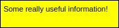
Notes add free text to the circuit, for example to explain how it works.