Examples
The repository has two kinds of examples:
- Python examples in the
examplesfolder build and simulate circuits in code. Most of them write a VCD file with all signals. - GUI example circuits in the
example_circuitsfolder are ready-made circuits to open in the DigSim application.
To run them, clone the repository and run the commands below from its root folder (see Run from source):
git clone https://github.com/freand76/digsim.git
cd digsim
The waveform images on this page are rendered from the VCD files that the examples write.
To look at the waveforms yourself, open the VCD file in
GTKWave or another VCD viewer, for example
gtkwave sr.vcd.
Python examples
SR latch
examples/example_sr.py
connects two push buttons to the set and reset inputs of an SR latch (built from two NOR
gates) and the latch output to an LED. The script presses the buttons in a fixed sequence,
and a callback prints the LED state every time it changes.
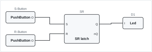
uv run python examples/example_sr.py
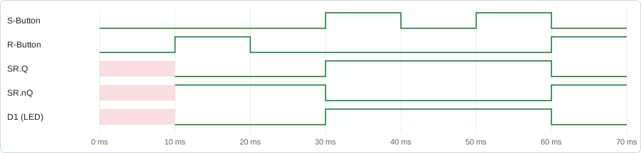
The left column is the simulation time in nanoseconds. Pressing set a second time does not change the output, the latch is already set:
        0:LED: 'D1' is OFF
Reset
 10000001:LED: 'D1' is OFF
Set
 30000002:LED: 'D1' is ON
Set (again)
Reset
 60000001:LED: 'D1' is OFF
The waveforms are written to sr.vcd. The latch output is unknown (red) until the first
reset:
Clock
examples/example_clock.py
connects a 20 Hz clock to an LED and simulates one second.
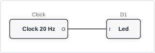
uv run python examples/example_clock.py
The LED toggles every 25 ms (half a 20 Hz period):
        0:LED: 'D1' is OFF
        0:LED: 'D1' is OFF
 25000000:LED: 'D1' is ON
 50000000:LED: 'D1' is OFF
 75000000:LED: 'D1' is ON
...
975000000:LED: 'D1' is ON
1000000000:LED: 'D1' is OFF
The first 300 ms of clock.vcd:

Save a circuit (pulse generator)
examples/load_save/example_save_circuit.py
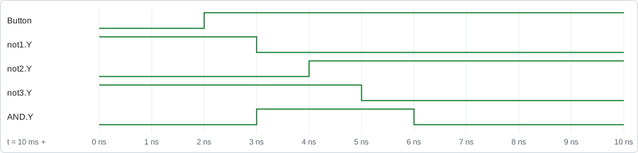
builds a pulse generator: a push button drives one AND input directly and the other through
three NOT gates. The circuit is simulated, saved to pulse_circuit.json, loaded into a new
circuit and simulated again.
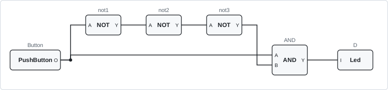
uv run python examples/load_save/example_save_circuit.py
When the button is pressed, both AND inputs are high for a moment, until the change has propagated through the three NOT gates (1 ns each). The LED is on for 3 ns. The second half of the output comes from the loaded copy of the circuit:
        0:LED: 'D' is OFF
        1:LED: 'D' is OFF
ON
 10000001:LED: 'D' is ON
 10000004:LED: 'D' is OFF
OFF
        1:LED: 'D' is OFF
  5000001:LED: 'D' is ON
  5000004:LED: 'D' is OFF
The waveforms in pulse.vcd, zoomed in on the button press at 10 ms, show the change
moving through the gates:
Load a circuit (logic gates)
examples/load_save/example_load_circuit.py
loads the circuit in
example_circuit.json:
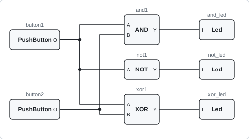
two buttons connected to an AND, a NOT and an XOR gate, each driving an LED. The script
presses the buttons in a sequence and prints the LED changes.
uv run python examples/load_save/example_load_circuit.py
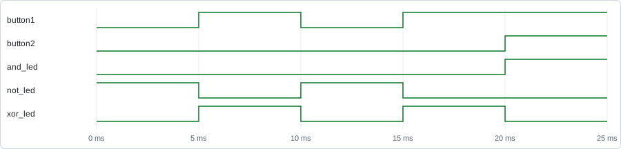
The ------------ lines show the button states (button1 button2) for the next step:
        1:LED: 'and_led' is OFF
        1:LED: 'xor_led' is OFF
        1:LED: 'not_led' is ON
------------ 10
  5000001:LED: 'not_led' is OFF
  5000001:LED: 'xor_led' is ON
------------ 00
 10000001:LED: 'not_led' is ON
 10000001:LED: 'xor_led' is OFF
------------ 10
 15000001:LED: 'not_led' is OFF
 15000001:LED: 'xor_led' is ON
------------ 11
 20000001:LED: 'and_led' is ON
 20000001:LED: 'xor_led' is OFF
The waveforms in circuit.vcd:
Verilog counter
The two examples in
examples/yosys_counter
simulate the 4-bit counter in
counter.v:
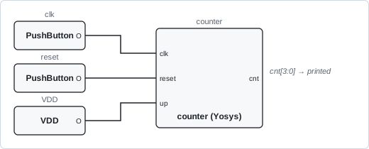
example_yosys_counter_netlist.pyloads the pre-synthesized netlistcounter.json.example_yosys_counter_verilog.pyloadscounter.vand synthesizes it on the fly.
Both connect push buttons to the clock and reset inputs and tie the up input high,
reset the counter and then clock it 16 times.
uv run python examples/yosys_counter/example_yosys_counter_netlist.py
uv run python examples/yosys_counter/example_yosys_counter_verilog.py
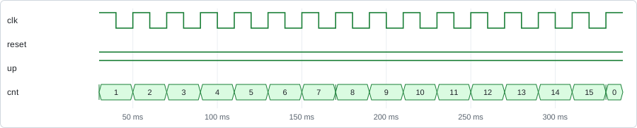
Both print the same output, the counter value before each clock pulse:
===================== Reset ==========================

counter
 - I:clk=0
 - I:reset=0
 - I:up=1
 - O:cnt=0

===================== Start ==========================

OUT 0
OUT 1
OUT 2
...
OUT 14
OUT 15
counter.vcd is started after the reset:
Synthesis (Fibonacci sequence)
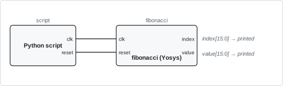
examples/synthesis/example_synthesis.py
synthesizes fibonacci.v,
a Fibonacci sequence generator, with Yosys from Python, loads the netlist as a component and
drives its clock and reset inputs directly from the script.
uv run python examples/synthesis/example_synthesis.py
Start synthesis of 'examples/synthesis/fibonacci.v'
Synthesis done!
...
Fibonacci sequence [0] value is 0
Fibonacci sequence [1] value is 1
Fibonacci sequence [2] value is 1
Fibonacci sequence [3] value is 2
Fibonacci sequence [4] value is 3
Fibonacci sequence [5] value is 5
...
Fibonacci sequence [14] value is 377
Fibonacci sequence [15] value is 610
The netlist is written to examples/synthesis/fibonacci.json and the waveforms to
fibonacci.vcd:

6502 CPU
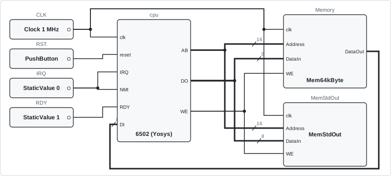
examples/yosys_6502/example_yosys_6502.py
simulates a synthesized 6502 CPU
(6502.json) connected to a 64 kB memory and a memory-mapped text output at address
0x8000. The program in the memory, built from
code.s,
writes "Hello World" to the text output, which prints each character.
uv run python examples/yosys_6502/example_yosys_6502.py
The simulation of 300 clock cycles takes less than a second:
cpu
 - I:clk=0
 - I:reset=0
 - I:DI=X
 - I:IRQ=0
 - I:NMI=0
 - I:RDY=1
 - O:AB=X
 - O:DO=X
 - O:WE=X
StringOutput [char]: 'H'
StringOutput [char]: 'e'
StringOutput [char]: 'l'
StringOutput [char]: 'l'
StringOutput [char]: 'o'
StringOutput [char]: ' '
StringOutput [char]: 'W'
StringOutput [char]: 'o'
StringOutput [char]: 'r'
StringOutput [char]: 'l'
StringOutput [char]: 'd'
StringOutput [line]: 'Hello World'
Waveforms are not written by default, since writing every signal in the CPU makes the
simulation slower. Add --vcd to write them to 6502.vcd, or --vcd <file> to choose the
file name:
uv run python examples/yosys_6502/example_yosys_6502.py --vcd
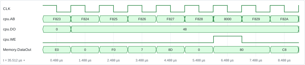
The waveforms below (values in hex) show the CPU fetching the program from F823 and
onwards, then writing 48, the character H, to the text output at address 8000:
To change the program, edit the assembly files and rebuild code.bin with compile.sh,
which needs the cc65 assembler and linker.
pytest testbenches
examples/pytest_tb tests
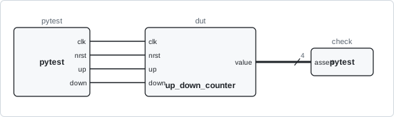
two Verilog designs with pytest: an 8-bit ALU (alu.v) and a 4-bit
up/down counter (up_down_counter.v). Each test module synthesizes its design in a fixture,
drives the inputs from Python and asserts on the outputs.
uv run --with pytest pytest -v examples/pytest_tb
examples/pytest_tb/test_alu_testbench.py::test_add PASSED
examples/pytest_tb/test_alu_testbench.py::test_sub PASSED
examples/pytest_tb/test_alu_testbench.py::test_and PASSED
examples/pytest_tb/test_alu_testbench.py::test_or PASSED
examples/pytest_tb/test_alu_testbench.py::test_xor PASSED
examples/pytest_tb/test_alu_testbench.py::test_logic_lshift PASSED
examples/pytest_tb/test_alu_testbench.py::test_logic_rshift PASSED
examples/pytest_tb/test_alu_testbench.py::test_arith_rshift PASSED
examples/pytest_tb/test_up_down_counter_testbench.py::test_no_count PASSED
examples/pytest_tb/test_up_down_counter_testbench.py::test_count_up PASSED
examples/pytest_tb/test_up_down_counter_testbench.py::test_count_down PASSED
examples/pytest_tb/test_up_down_counter_testbench.py::test_up_precedence PASSED
examples/pytest_tb/test_up_down_counter_testbench.py::test_reset_after_count PASSED
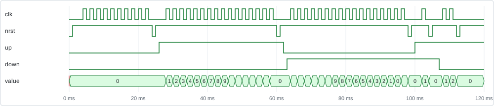
The tests write alu_test.vcd and up_down_counter_test.vcd. The counter tests, one after
the other: no counting, counting up to 15 and wrapping to 0, counting down, and resets:
GUI example circuits
Open a circuit in the application with --load, then press Start Simulation (or
Space):
uv run -m digsim.app --load example_circuits/counter_yosys_netlist.circuit
You can also use Load Circuit in the application. See GUI Application for how to work with the editor.
Verilog counter
counter_yosys_netlist.circuit and counter_yosys_verilog.circuit are the same circuit:
the Verilog counter as a Yosys component, loaded from the netlist or
directly from counter.v. Notes in the circuit explain each part:
- a 5 Hz clock drives the counter and an LED,
- a push button resets the counter (shortcut 1),
- a switch enables counting (shortcut 2),
- a hex digit shows the counter value,
- a logic analyzer shows the clock, button, switch and the four counter bits, connected through Wire Sources/Sinks and a bus splitter,
- a buzzer sounds while the reset button is pressed.
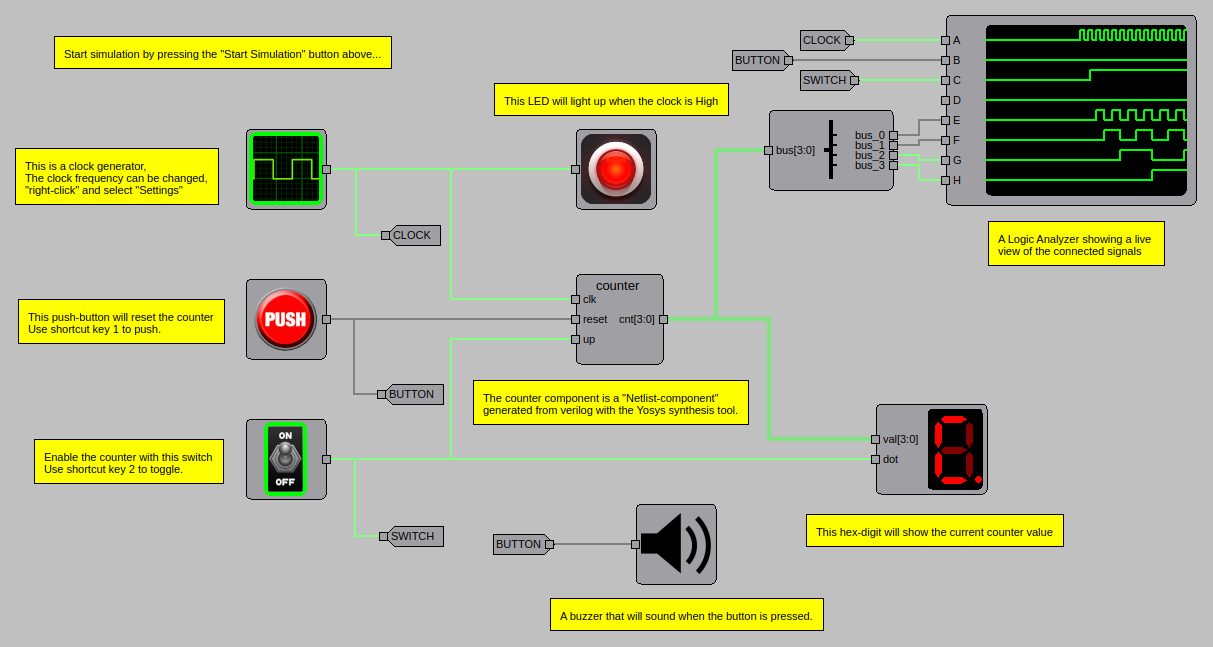
Turn on the switch to start counting.
74162 counter
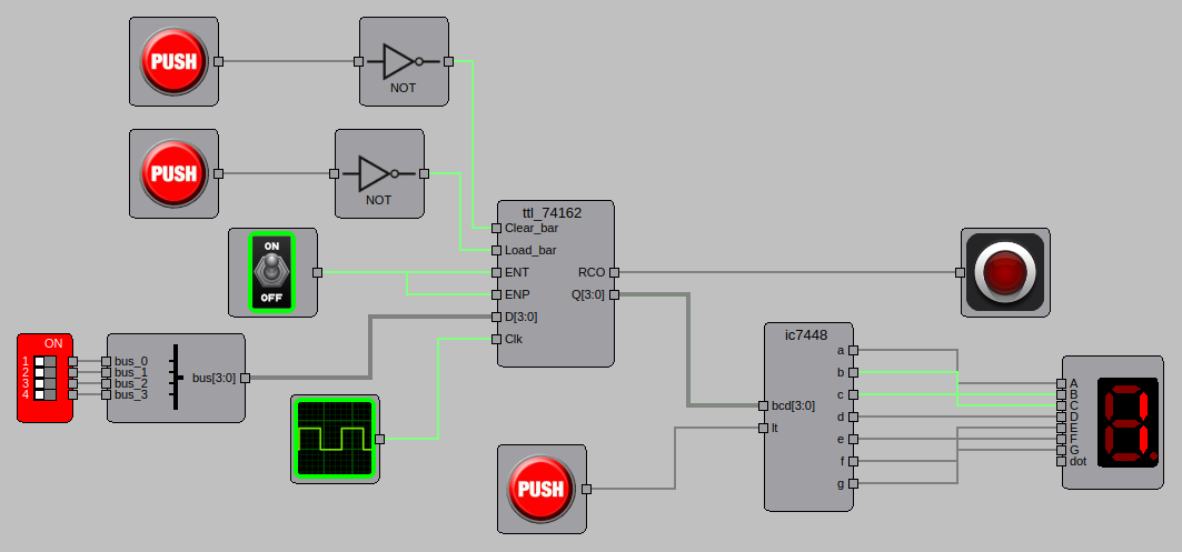
74162_counter.circuit rebuilds a classic counter board with two ICs from the built-in IC
library: a 74162 synchronous decade counter and a 7448 BCD to 7-segment decoder.
- A 5 Hz clock drives the counter, and the switch enables counting (
ENPandENT). - The 7448 decodes the counter value to the 7-segment display.
- The LED shows the counter's ripple-carry output (
RCO), which is high on the count of 9. - The DIP switch sets a value that is loaded with one push button (
Load), and another push button clears the counter (Clear). Both inputs are active low, hence the NOT gates. - The third push button drives the 7448 lamp-test input (
lt).
Shift register
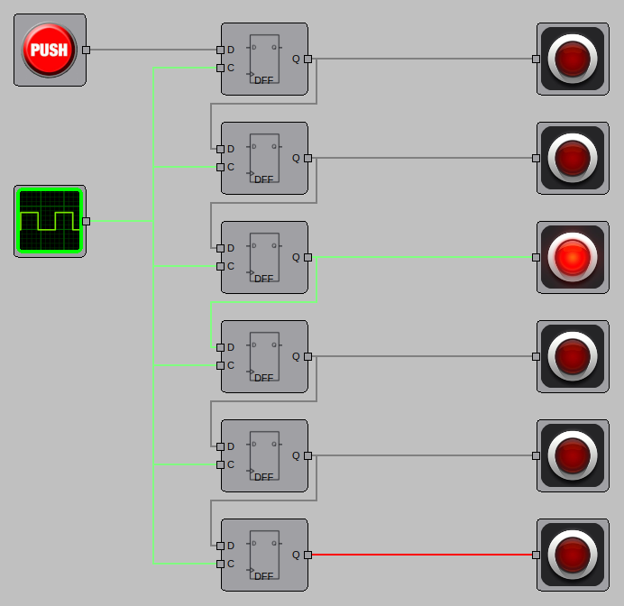
shift_register.circuit is a 6-bit shift register: six D flip-flops in a chain, clocked
by a 5 Hz clock, with an LED on each output. Press the push button to shift ones into the
register and watch them move along the LEDs.
Buzzers
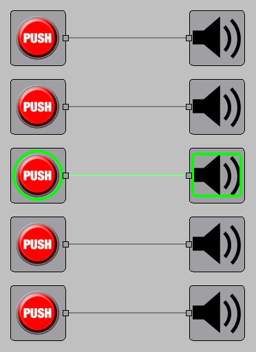
buzzers.circuit has five push buttons, each connected to a buzzer with its own tone
(C, D, E, F and G). Press the buttons, or the shortcut keys 1 to 5, while the
simulation runs to play a tune.
Regenerating the images
The images on this page are generated by
docs/scripts/generate_examples.py,
which runs the examples, renders the waveforms from their VCD files and takes screenshots
of the GUI circuits:
uv run --with pytest python docs/scripts/generate_examples.py