Creating Components
This guide shows how to write your own DigSim component, step by step, using two examples:
XNOR, a logic gate. First as a component for Python circuits, then in the GUI with an image as its symbol.LedBar, a row of LEDs that shows the bits of a bus. In the GUI it is drawn by code, so it can show its current value.

Info
Both components are part of DigSim, so you can try them in the application and read the finished code:
XNORis in_gates.py, extended from the two-input version in this guide to 2 to 8 inputs, like the other gates.LedBaris in_led_bar.py, and its GUI object in_led_bar_object.py.
Part 1 works in your own project, without changing DigSim. Part 2 adds the component to the DigSim application itself, which means changing DigSim's source code. Contributions of new components are welcome, see Contributing.
Tip
If your component can be described in Verilog, you may not need to write a component class at all: a Yosys component turns a Verilog module into a component.
How components work
A component has ports, and wires connect an output port of one component to input
ports of other components. A port value is 0, 1, a number for buses wider than one
bit, or "X" when the value is unknown (for example before the circuit is initialized).
The simulation is event driven. When a component sets an output, an event is scheduled
after the port's delay (1 ns by default). When the event happens, the new value travels
along the wires, and every component with a changed input port gets its update() method
called, which may set new outputs, and so on.
Ports
Ports live in digsim.circuit.components.atoms:
| Port | Use |
|---|---|
PortIn |
An input that calls the component's update() when it changes. |
PortWire |
An input that does not call update(), for inputs that are only read when another input changes, such as the D input of a flip-flop. |
PortOutDelta |
An output that changes after a delay (delay_ns, default 1 ns). Use this for logic. |
PortOutImmediate |
An output that changes at once, for inputs controlled by the user, such as buttons. |
PortMultiBitWire |
A bus port that also gives access to its single bits (get_bit()). |
Ports take a width argument for buses, for example PortIn(self, "I", width=8). A port
added with add_port() becomes an attribute with the port's name, so self.add_port(PortIn(self, "A"))
can be used as self.A afterwards.
Base classes
| Base class | Use |
|---|---|
Component |
Most components. |
CallbackComponent |
Components that should notify someone when they change, typically outputs such as LEDs. The callback is called from update(), and the GUI uses it to repaint the component. |
MultiComponent |
Components built from other components, such as the SR latch, built from two NOR gates. |
Methods to implement
| Method | Called |
|---|---|
__init__() |
Create ports with add_port() and store settings with parameter_set(). |
default_state() |
When the circuit is initialized (circuit.init()). Set the initial output values here. |
update() |
When a PortIn input changes. Compute and set the outputs. |
get_parameters() |
A class method describing the settings of the component, see Parameters. |
reconfigure() |
After the settings of a placed component have changed in the GUI. |
Part 1: A component for Python circuits
Step 1: Write the component class
An XNOR gate has two inputs and an output that is high when the inputs are equal. Put it in
a module of your own, for example my_components.py:
from digsim.circuit.components.atoms import Component, PortIn, PortOutDelta


class XNOR(Component):
    """XNOR logic gate: Y is high when A and B are equal"""

    def __init__(self, circuit, name=None):
        super().__init__(circuit, name)
        self.add_port(PortIn(self, "A"))
        self.add_port(PortIn(self, "B"))
        self.add_port(PortOutDelta(self, "Y"))

    def update(self):
        if self.A.value == "X" or self.B.value == "X":
            self.Y.value = "X"
        elif self.A.value == self.B.value:
            self.Y.value = 1
        else:
            self.Y.value = 0
nameis optional. Without it the component is named after its class, and DigSim adds_1,_2, ... when the name is already taken in the circuit.- Handle
"X"on the inputs, so that unknown values propagate instead of being treated as0.
Step 2: Use it in a circuit
Your component is used like the built-in ones:
from digsim.circuit import Circuit
from digsim.circuit.components import Led, PushButton

from my_components import XNOR


def led_changed(led):
    state = "ON" if led.I.value == 1 else "OFF"
    print(f"{led.circuit.time_ns:>9} ns: {led.name()} is {state}")


circuit = Circuit()
button_a = PushButton(circuit, "A")
button_b = PushButton(circuit, "B")
xnor = XNOR(circuit)
led = Led(circuit, "led", callback=led_changed)

button_a.O.wire = xnor.A
button_b.O.wire = xnor.B
xnor.Y.wire = led.I

circuit.init()
circuit.run(ms=1)  # A=0, B=0: equal, LED on
button_a.push()
circuit.run(ms=1)  # A=1, B=0: different, LED off
button_b.push()
circuit.run(ms=1)  # A=1, B=1: equal, LED on
        0 ns: led is OFF
        1 ns: led is ON
  1000001 ns: led is OFF
  2000001 ns: led is ON
The LED is off at 0 ns because the XNOR output is still unknown. It turns on 1 ns later, after the gate delay.
Step 3: Add parameters
Parameters are settings chosen when a component is created, such as the number of LEDs in
the LED bar. Store each parameter with parameter_set() and describe it in
get_parameters():
from digsim.circuit.components.atoms import CallbackComponent, PortIn


class LedBar(CallbackComponent):
    """A row of LEDs showing the bits of a bus"""

    def __init__(self, circuit, name=None, width=8):
        super().__init__(circuit, name, callback=None)
        self.add_port(PortIn(self, "I", width=width))
        self.parameter_set("width", width)

    def lit(self):
        """The state of each LED, bit 0 first"""
        width = self.parameter_get("width")
        value = self.I.value
        if value == "X":
            return [False] * width
        return [bool((value >> bit) & 1) for bit in range(width)]

    @classmethod
    def get_parameters(cls):
        return {
            "width": {
                "type": "int",
                "min": 1,
                "max": 16,
                "default": 8,
                "description": "Number of LEDs",
            },
        }
Important
Every parameter name must also be an argument of __init__(). When a circuit is saved,
DigSim stores the parameters, and when it is loaded the component is created again with
them as keyword arguments: LedBar(circuit=circuit, width=8).
LedBar is a CallbackComponent. It doesn't compute anything, but the callback lets a
user of the component (and the GUI, in part 2) know when its input has changed.
Step 4: Test it
Components are plain Python, so they are easy to test with pytest:
from digsim.circuit import Circuit

from my_components import XNOR


def test_xnor():
    circuit = Circuit()
    xnor = XNOR(circuit)
    circuit.init()
    for a, b, y in [(0, 0, 1), (0, 1, 0), (1, 0, 0), (1, 1, 1)]:
        xnor.A.value = a
        xnor.B.value = b
        circuit.run(ns=10)
        assert xnor.Y.value == y
Inputs that are not driven by another component can be set directly, as here.
Saving circuits with your own components
circuit.to_json_file() stores each component's type as its module path and class name,
leaving out module names that start with _. A component in my_components.py is stored
as my_components.XNOR, so my_components must be importable when the circuit is
loaded again.
Part 2: Adding the component to the GUI
The GUI can only show components that are part of DigSim, so this part changes DigSim's source code. Start with a development setup. These are all the steps needed to get a component into the component selector:
- Add the component to DigSim
- Export it from
digsim.circuit.components - Create a GUI object, either with an image or drawn by code
- Register the GUI object
- Add the component to the component selector
- Check the settings dialog
- Try it
1. Add the component to DigSim
Move the component class to its own module in
src/digsim/circuit/components,
for example _xnor.py and _led_bar.py. Module names start with _, and the code in
DigSim is type annotated, so the class looks like this:
# src/digsim/circuit/components/_xnor.py
from __future__ import annotations

from typing import TYPE_CHECKING

from .atoms import Component, PortIn, PortOutDelta


if TYPE_CHECKING:
    from digsim.circuit import Circuit


class XNOR(Component):
    """XNOR logic gate: Y is high when A and B are equal"""

    def __init__(self, circuit: Circuit, name: str | None = None) -> None:
        super().__init__(circuit, name)
        ...

    def update(self) -> None: ...
2. Export the component
Add the class to
src/digsim/circuit/components/__init__.py:
from ._led_bar import LedBar
from ._xnor import XNOR
Both the GUI and saved circuit files find components by their name in
digsim.circuit.components. A saved XNOR gate is stored as
digsim.circuit.components.XNOR.
3a. A GUI object with an image
Each component in the GUI is shown by a GUI object, a class in
src/digsim/app/gui_objects.
For a component with a picture as its symbol, subclass ImageObject and name the image.
Gates use GateImageObject, which also hides the port names. In
_image_objects.py:
class ImageObjectXNOR(GateImageObject):
    """The class for a XNOR image component placed in the GUI"""

    IMAGE_FILENAME = "images/XNOR.png"
- Put the image in
src/digsim/app/gui_objects/images. The existing symbols are PNG files about 70 pixels wide. Files in that folder are included in the package (seeMANIFEST.in). - Set
ACTIVE_IMAGE_FILENAMEas well to show another image while the component'sactiveproperty isTrue, the way the LED lights up. - The same image is used in the component selector.
3b. A GUI object drawn by code
To show the state of a component, draw it in paint_component(). Subclass
ComponentObject, in a new module such as _led_bar_object.py:
from __future__ import annotations

from typing import TYPE_CHECKING

from PySide6.QtCore import QPoint, QSize, Qt
from PySide6.QtGui import QPainter

from digsim.circuit.components import LedBar
from digsim.circuit.components.atoms import Component

from ._component_object import ComponentObject


if TYPE_CHECKING:
    from digsim.app.model import AppModel


class LedBarObject(ComponentObject):
    """The class for a LED bar component placed in the GUI"""

    LED_WIDTH = 8
    LED_HEIGHT = 24
    LED_GAP = 4

    def __init__(
        self, app_model: AppModel, component: Component, xpos: float, ypos: float
    ) -> None:
        super().__init__(app_model, component, xpos, ypos)
        self.update_size()

    @property
    def component(self) -> LedBar:
        component = self._component
        assert isinstance(component, LedBar)
        return component

    def update_size(self) -> None:
        leds = len(self.component.lit())
        self.width = 2 * self.inport_x_pos() + 40 + leds * (self.LED_WIDTH + self.LED_GAP)
        self.update_ports()

    def paint_component(self, painter: QPainter) -> None:
        self.paint_component_base(painter)
        self.paint_component_name(painter)
        # Draw the most significant bit to the left
        xpos = int(self.object_pos.x() + self.inport_x_pos() + 30)
        ypos = int(self.object_pos.y() + self.height / 2 - self.LED_HEIGHT / 2 + 8)
        for led_on in reversed(self.component.lit()):
            self._paint_led(painter, xpos, ypos, led_on)
            xpos += self.LED_WIDTH + self.LED_GAP

    @classmethod
    def _paint_led(cls, painter: QPainter, xpos: int, ypos: int, led_on: bool) -> None:
        painter.setPen(Qt.GlobalColor.black)
        painter.setBrush(Qt.GlobalColor.red if led_on else Qt.GlobalColor.darkRed)
        painter.drawRect(xpos, ypos, cls.LED_WIDTH, cls.LED_HEIGHT)

    @classmethod
    def paint_selectable_component(cls, painter: QPainter, size: QSize, name: str) -> None:
        xpos = (size.width() - 6 * (cls.LED_WIDTH + cls.LED_GAP)) // 2
        for led_on in [True, False, True, True, False, False]:
            cls._paint_led(painter, xpos, 20, led_on)
            xpos += cls.LED_WIDTH + cls.LED_GAP
        cls.paint_selectable_component_name(painter, QPoint(0, 0), size, name)
| Method | Purpose |
|---|---|
paint_component(painter) |
Draws the placed component with a QPainter. paint_component_base() draws the standard rounded box, paint_component_name() the name. The box is self.rect(), positioned at self.object_pos. |
paint_selectable_component(painter, size, name) |
A class method that draws the component's icon in the component selector, in a size sized area. |
update_size() |
Called when the component's settings change. Set self.width and self.height, then call update_ports() to move the ports. |
component |
Override it to return the component's own type, so type checkers know its methods. |
The GUI repaints a CallbackComponent after its update() runs, which is why LedBar
subclasses it. A plain Component is only repainted when something else in the circuit
changes.
Note
Qt drawing functions that take whole pixels, such as drawRect(x, y, w, h), need
int values, so use int() around calculated positions.
4. Register the GUI object
Map the component's class name to its GUI object in CLASS_NAME_TO_COMPONENT_OBJECT in
_gui_object_factory.py,
and import the GUI object class there:
CLASS_NAME_TO_COMPONENT_OBJECT: dict[str, type[ComponentObject]] = {
    ...
    "XNOR": ImageObjectXNOR,
    "LedBar": LedBarObject,
}
5. Add it to the component selector
Add a SelectableComponentWidget for the component in ComponentSelection in
src/digsim/app/gui/_component_selection.py.
The order of the lines is the order in the selector, under the group headings ("Input",
"Output", "Gates", ...). display_name sets the label, which is the class name otherwise:
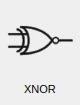
layout.addWidget(SelectableComponentWidget("XNOR", self, circuit_area))
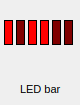
layout.addWidget(SelectableComponentWidget("LedBar", self, circuit_area, display_name="LED bar"))
6. The settings dialog
When a component is added in the GUI, a settings dialog is created from
get_parameters(), with one input per parameter (components without parameters are
placed right away). The parameter's type selects the input:
type |
Input | Keys |
|---|---|---|
int |
Slider | min, max, default |
intrange |
Slider over a list of values | range, default_index |
bool |
Checkbox | default |
str |
Text field | default, single_line (one line instead of a text box), invalid_list (values not allowed) |
list |
Drop-down | items |
width_pow2 |
Slider from 0 to 2width-1, following a width parameter |
default |
width_bool |
One checkbox per bit, following a width parameter |
default |
component_name |
Drop-down that selects another component class | component_list (class name to description) |
ic_name |
Drop-down with the built-in ICs | |
path |
File dialog (when it is the only parameter) | fileinfo (file filter) |
Every parameter needs a description, the label shown in the dialog. Add
"reconfigurable": True to let the user change the parameter later, with Settings in
the component's context menu. Afterwards, the component's reconfigure() method and the GUI
object's update_size() are called.
Interactive components
Components that the user operates while the simulation runs, like buttons and switches:
- return
Truefrom thehas_actionproperty, to get a hand cursor over the component while the simulation runs, - implement
onpress()andonrelease(), called when the component is pressed and released with the mouse (or a keyboard shortcut) while the simulation runs, - use
PortOutImmediateoutputs, - return the state from the
activeproperty, to useACTIVE_IMAGE_FILENAME.
See PushButton and OnOffSwitch in src/digsim/circuit/components for examples. In the
GUI object, single_click_action() handles clicks while the simulation is stopped, and
add_context_menu_action(menu, parent) adds entries to the context menu.
7. Try it
- Start the application from the source tree:
uv run -m digsim.app. - Add the component from the selector, connect it, and run the simulation.
- Save the circuit, clear it, and load it again, to check that the parameters are restored.
- Add a test for the component in
tests/, and run the checks described in Contributing. - Document the component in the component reference, with
its image in
docs/images/components/.