Your First Circuit
This guide walks you through building and simulating a small circuit in the DigSim application: two switches connected to an AND gate that lights an LED. It takes about ten minutes, and you will learn the basics that all larger circuits are built with:
- adding components to the circuit,
- connecting them with wires,
- running the simulation and interacting with it,
- saving the circuit.
You need DigSim installed, see Installation. The GUI Reference describes everything in the application in more detail.
1. Start DigSim
Start the application from a terminal:
digsim-logic-simulator
Or, without installing anything, with uvx digsim-logic-simulator.
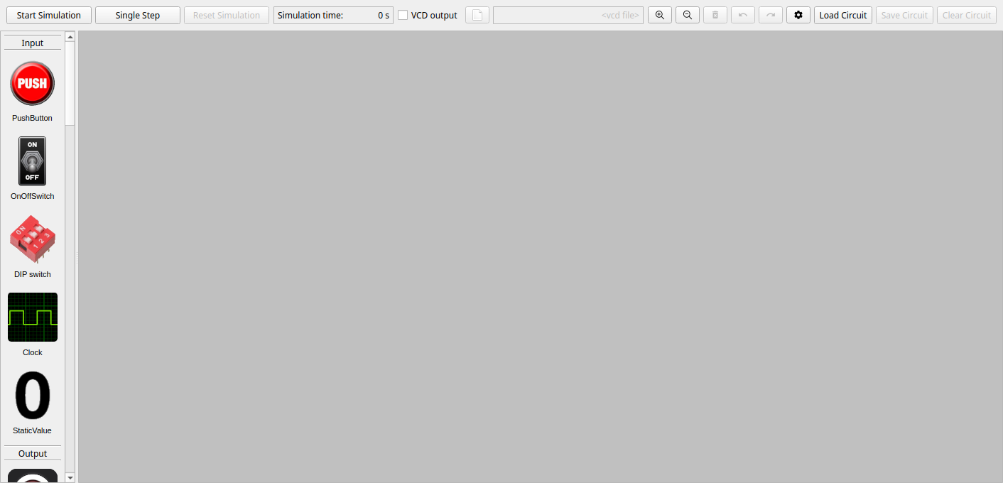
The window has three parts:
- Component selection (left): all components, grouped into Input, Output, Gates and more. Scroll down to see them all.
- Circuit area (the large gray area): where you build the circuit.
- Control area (top): starts and stops the simulation, and loads and saves circuits.
2. Add a switch
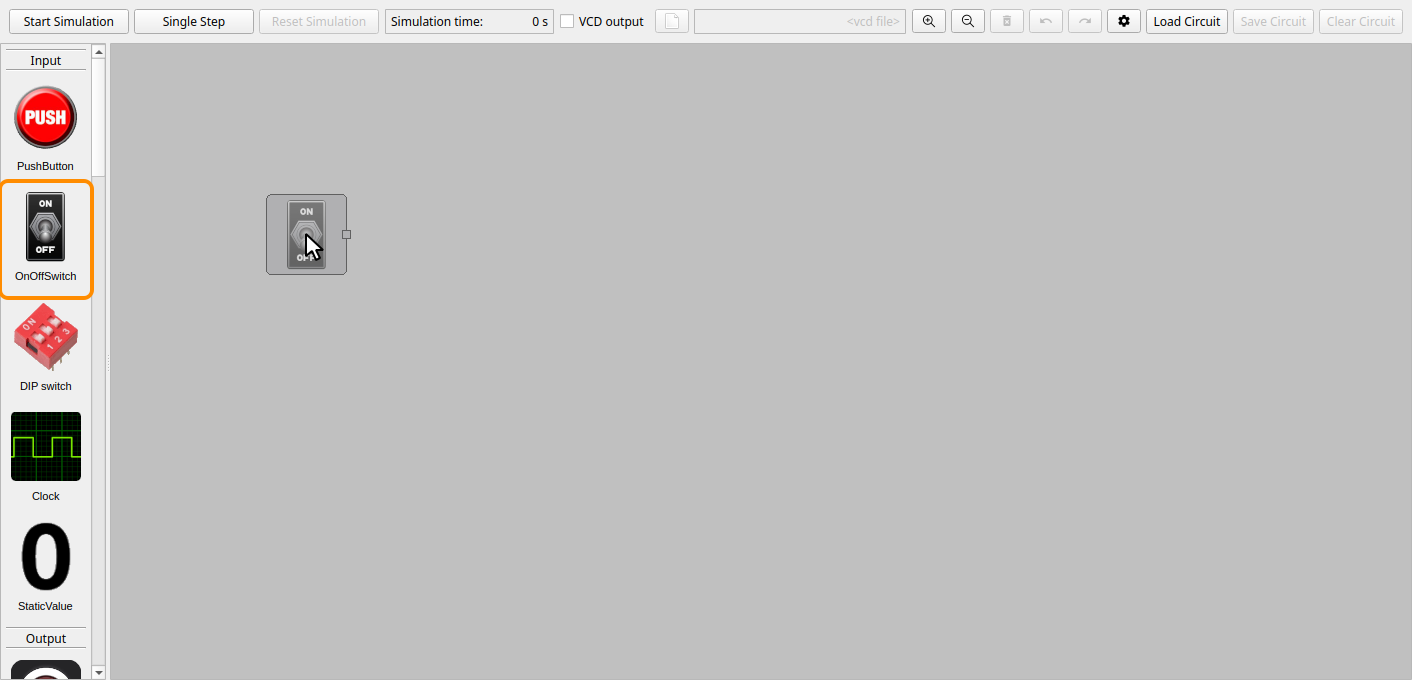
Find OnOffSwitch in the Input group. Drag it into the circuit area and release the mouse button where you want it. While you drag, a preview shows where the switch will be placed.
Tip
You can also double-click a component in the component selection. It is then placed in the upper left part of the circuit area.
3. Add a second switch
Add one more switch in the same way, below the first one.
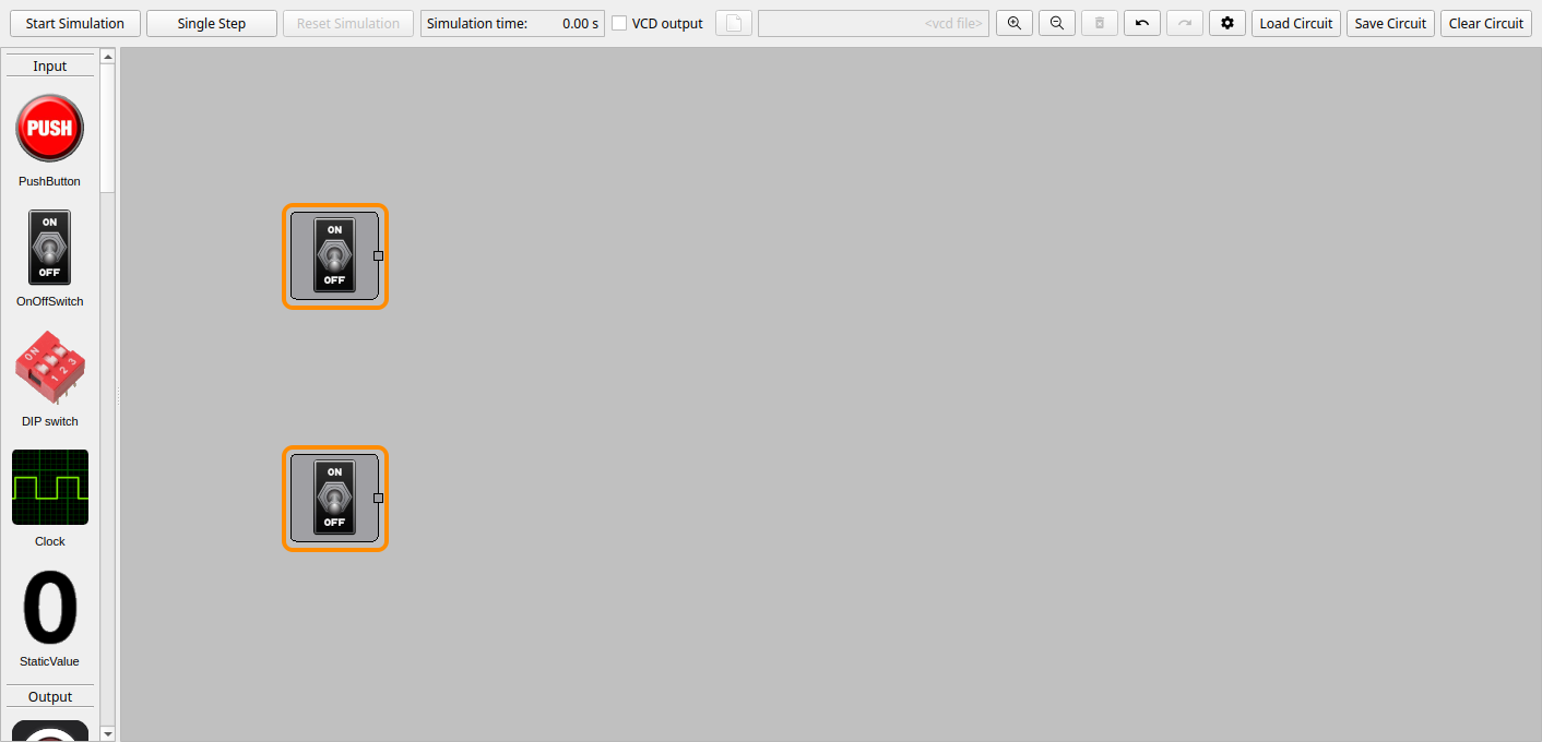
To move a component, drag it with the mouse. To remove one, click it to select it and press Del. If you make a mistake, Ctrl+Z undoes it.
4. Add an AND gate
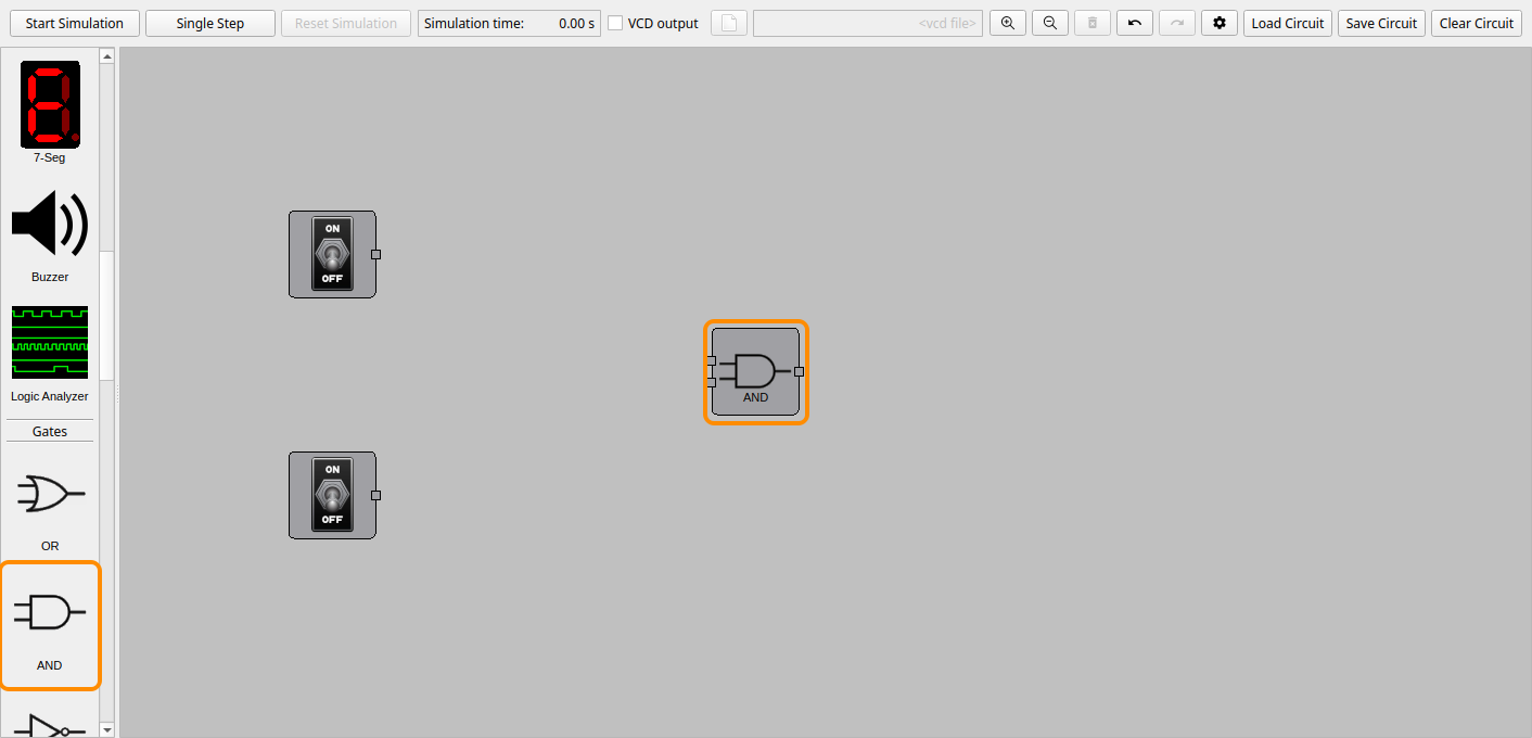
Scroll down to the Gates group and drag an AND gate into the circuit area, between the switches and the right edge.
Some components have settings, and they open a settings dialog when they are added. For the AND gate, you choose the number of inputs. Keep 2 and click OK.
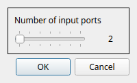
The gate has two inputs on its left side, A and B, and an output Y on its right side.
5. Add an LED
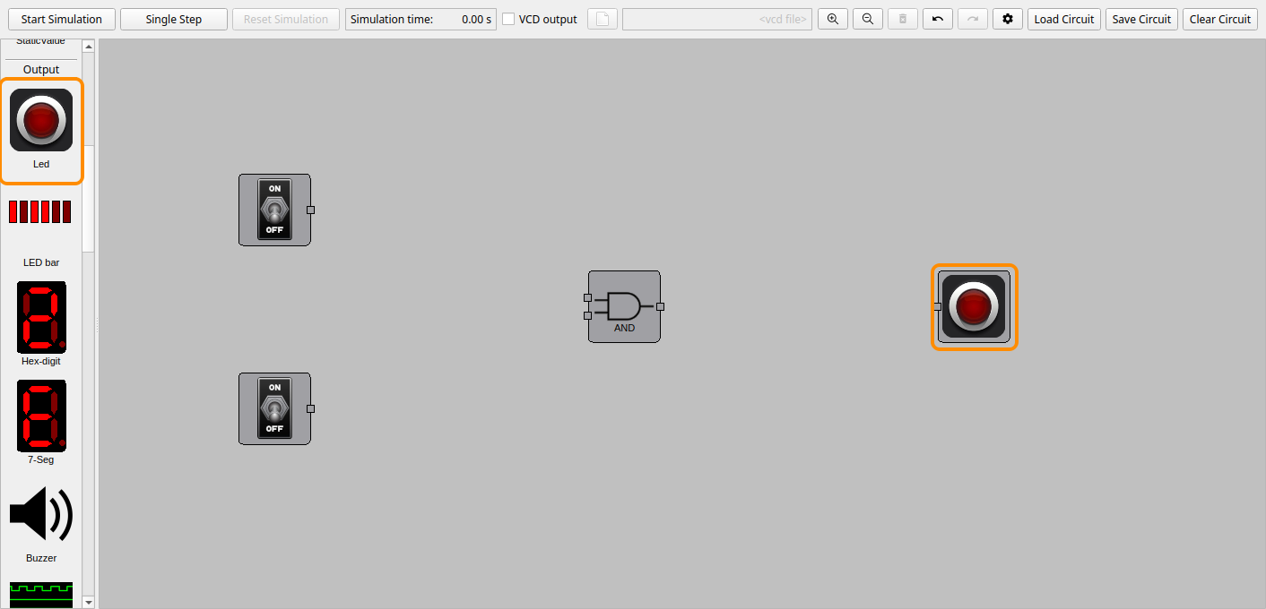
Drag an LED from the Output group to the right of the AND gate. It has a single input on its left side.
6. Connect the wires
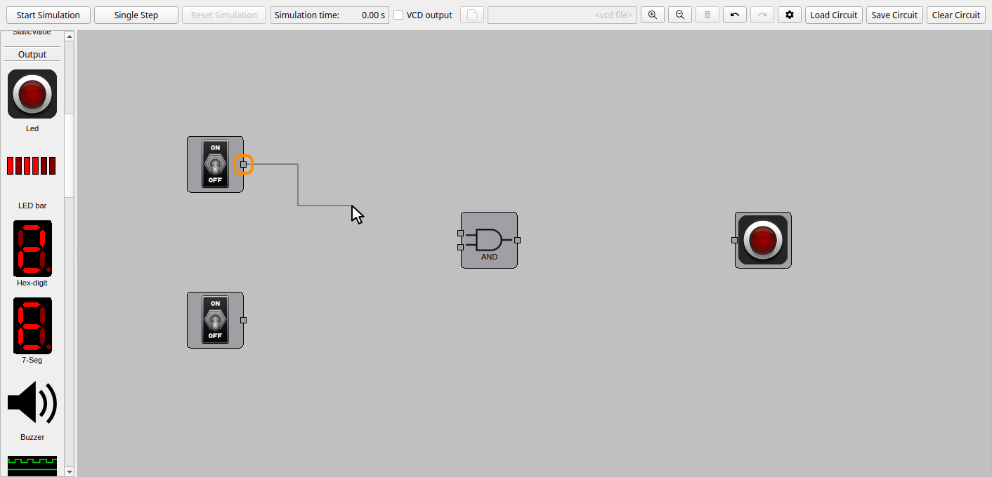
Wires connect the small squares on the sides of the components, called ports. Outputs are on the right side of a component and inputs on the left side.
To draw a wire, click a port, and then click the port you want to connect it to. Start with the output of the upper switch: click its port. A wire follows the mouse pointer until you click the other end, input A of the AND gate.
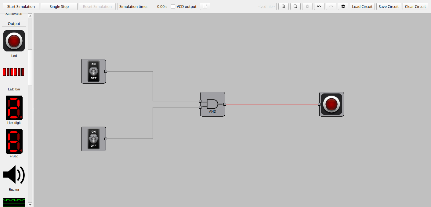
Connect the rest of the circuit in the same way:
- the output of the lower switch to input B of the AND gate,
- the output Y of the AND gate to the input of the LED.
Tip
Press Esc to cancel a wire that you have started. One output can drive any number of inputs, but each input can only have one wire to it.
7. Start the simulation
Click Start Simulation in the control area, or press Space. The simulation time starts counting, and the button changes to Stop Simulation.
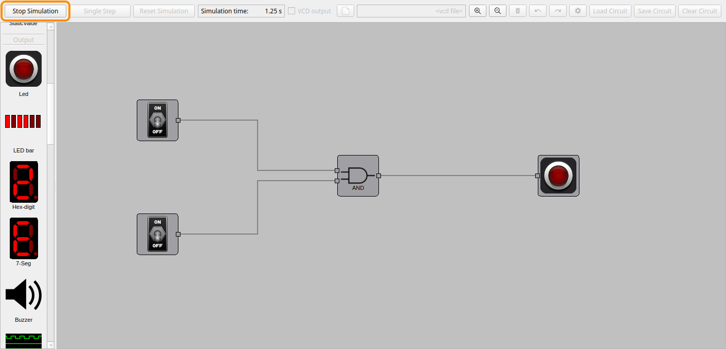
The wires now show the logic level they carry: dark gray for 0 and green for 1. A red wire has an undefined value, for example from an input that is not connected to anything. While the simulation runs, the circuit can't be edited.
8. Try it out
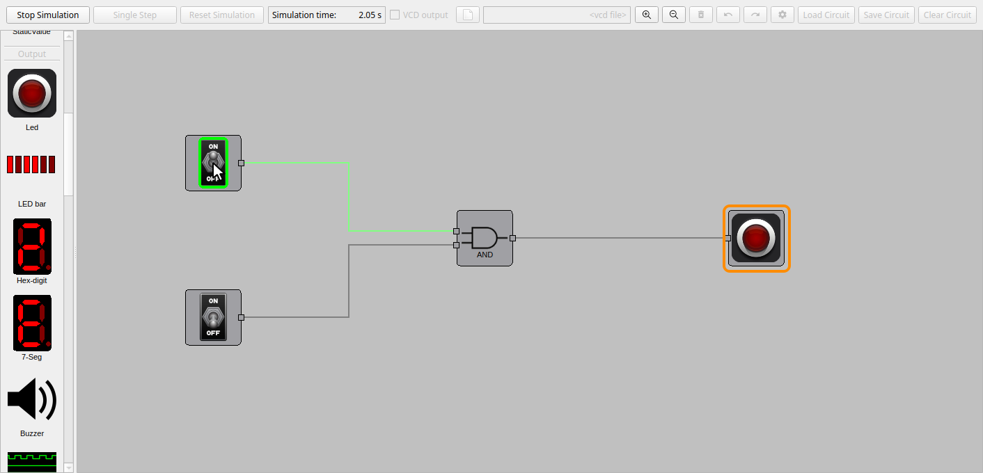
Click the upper switch to turn it on. Its wire turns green, but the LED stays off: an AND gate only outputs 1 when both its inputs are 1.
Now click the lower switch. Both inputs of the AND gate are 1, and the LED lights up.
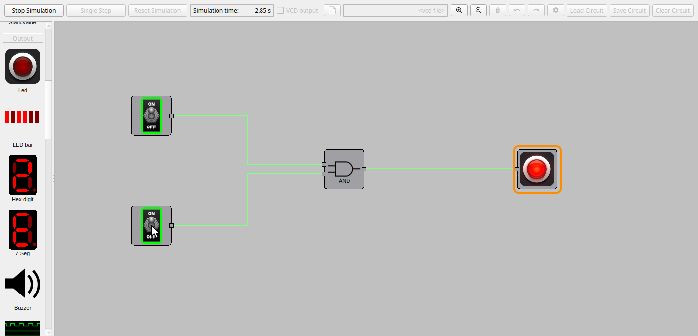
Click the switches a few times and check that the LED follows the truth table of an AND gate:
| Upper switch | Lower switch | LED |
|---|---|---|
| Off | Off | Off |
| On | Off | Off |
| Off | On | Off |
| On | On | On |
9. Stop and save the circuit
Click Stop Simulation (or press Space). Then click Save Circuit and choose a
file name, for example first_circuit.circuit.
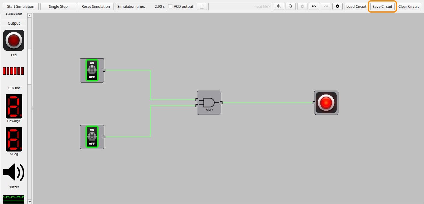
To open the circuit again later, click Load Circuit, or start DigSim with the file:
digsim-logic-simulator --load first_circuit.circuit
Next steps
Now that you know the basics, here are some things to try:
- Other gates: delete the AND gate (click it and press Del), add an OR or XOR gate instead, connect it, and compare their truth tables.
- Keyboard shortcuts: right-click a switch and choose Shortcut to toggle it with a number key while the simulation runs.
- Waveforms: check VCD output before you start the simulation, to record all signals to a file that you can view in GTKWave.
- More components: clocks, flip-flops, hex displays and more are described in the GUI Reference.
- Example circuits: load the circuits in the
example_circuitsfolder, described in Examples. - Your own Verilog: turn a Verilog module into a component, see Verilog and Yosys.