Your First Verilog Component
This guide walks you through making a component of your own in Verilog, without leaving DigSim. You start a new circuit, add a Verilog component with a new Verilog file, write a half adder in the editor, and try it with two switches and two LEDs. It takes about ten minutes, and you will learn to:
- add a Verilog component with a new Verilog file,
- write a small design in the Verilog editor,
- synthesize it, so that the component gets the ports and the behavior of your design,
- connect the new component and run it.
You need DigSim installed, see Installation. If you haven't used DigSim before, start with Your First Circuit. No Verilog tools are needed: DigSim comes with Yosys.
1. Start a new circuit
Start DigSim:
digsim-logic-simulator
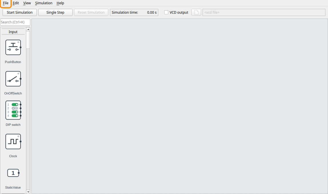
The circuit area is empty when DigSim starts. If you already have a circuit open, choose File > New (or File > New Tab).
2. Add a Verilog component
Scroll down to the IC / Verilog group in the component selection, and drag Verilog into the middle of the circuit area. A Verilog component gets its behavior from a Verilog design, and DigSim asks where the design comes from:
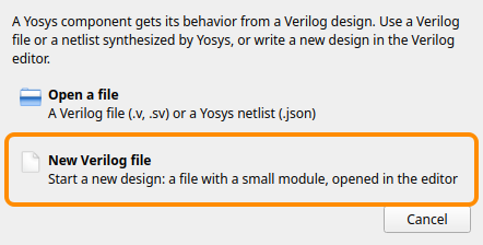
Click New Verilog file, and choose a folder and a file name in the file dialog, for
example half_adder.v. Keep the Verilog file in the same folder as the circuit that you
save in step 9, so that they stay together. On Linux, choose a folder outside /tmp:
Yosys runs as WebAssembly in DigSim and can't read the files there. DigSim tells you if
you choose a folder that it can't use.
The name of the file is the name of the module: half_adder.v gets the module
half_adder. DigSim never replaces a file that exists. If you choose one, it asks if you
want to use it as it is.
3. The settings of the component
The new component is selected, and its settings are in the settings pane, to the right of the circuit area. If the pane isn't shown, press F4 (or choose View > Settings Pane). Keep both boxes unchecked.
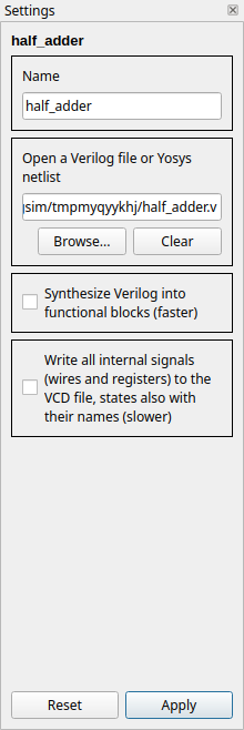
- Synthesize Verilog into functional blocks simulates the design faster, with blocks like adders and registers instead of gates. That matters for large designs.
- Write all internal signals to the VCD file records the wires and registers inside the design too, when you record a VCD file.
Both can be changed later: select the component, check the box in the settings pane, and click Apply.
4. The new component and its Verilog
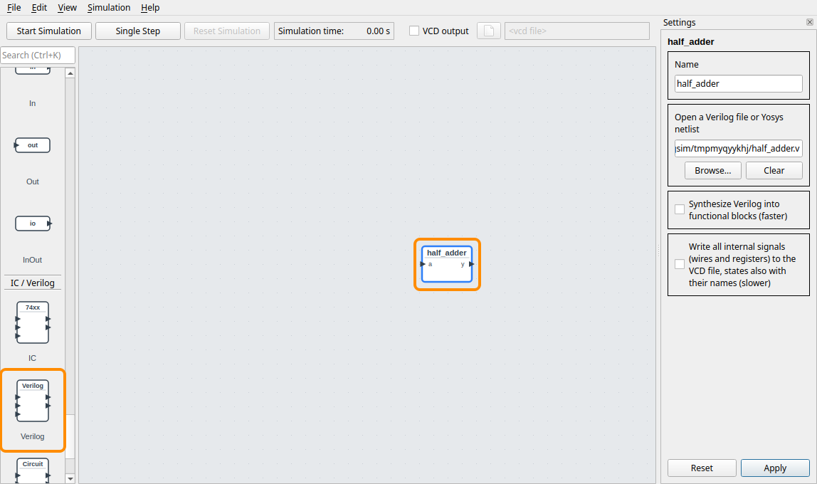
DigSim creates the file with a small module and places the component. It has the input
a and the output y of that module:
The Verilog editor opens in a window of its own, with the new file:
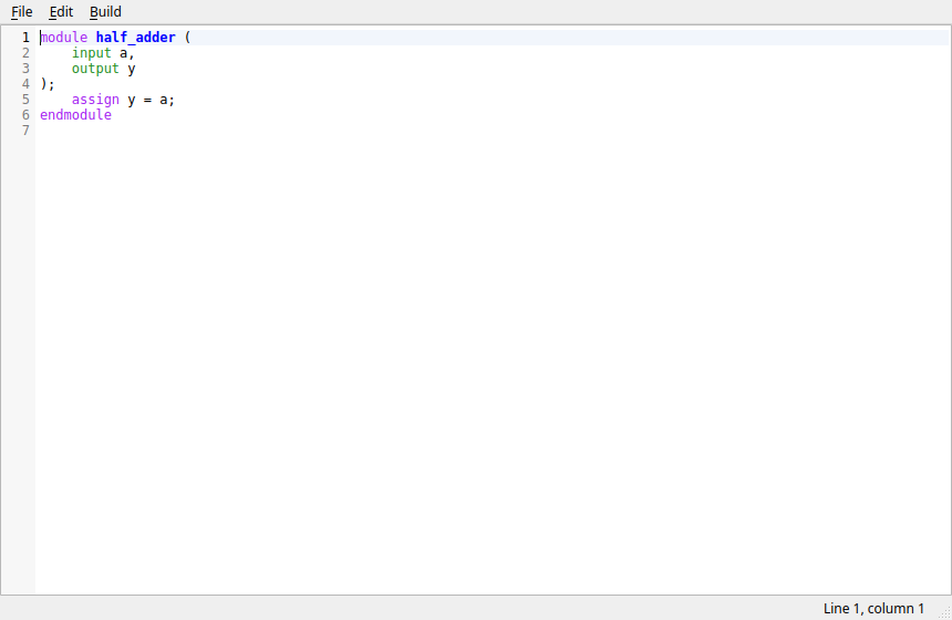
module half_adder (
    input a,
    output y
);
    assign y = a;
endmodule
The module just passes a on to y. The ports are listed between the brackets after
the module name, and assign sets an output from the inputs.
5. Write the half adder
A half adder adds two bits, a and b. The result needs two bits: sum, the low bit,
and carry, the high bit.
| a | b | carry | sum | a + b |
|---|---|---|---|---|
| 0 | 0 | 0 | 0 | 0 |
| 0 | 1 | 0 | 1 | 1 |
| 1 | 0 | 0 | 1 | 1 |
| 1 | 1 | 1 | 0 | 2 |
sum is 1 when exactly one of the inputs is 1: that's XOR, ^ in Verilog. carry is 1
when both are 1: that's AND, &. Replace the module in the editor with this one:
module half_adder (
    input a,
    input b,
    output sum,
    output carry
);
    assign sum = a ^ b;
    assign carry = a & b;
endmodule
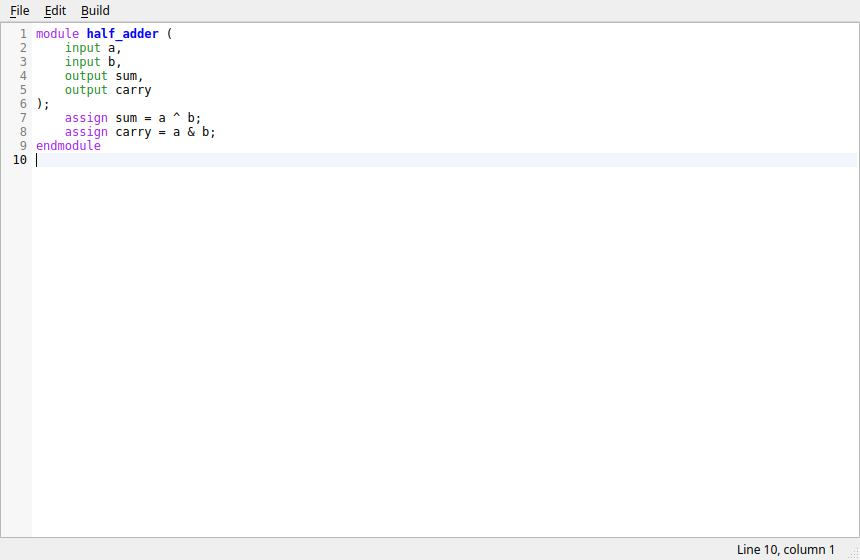
The editor indents a new line like the one before when you press Enter, and
Build > Format (Ctrl+Shift+I) indents the whole file. The window title gets a *
while the text has changes that are not saved.
6. Synthesize
Choose Build > Synthesize, or press Ctrl+B. The editor saves the file, and Yosys turns the module into gates that DigSim simulates.
The ports of the module are not the ones the component has, so DigSim lists the changes and asks first:
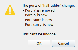
Click OK. New ports are added to the component, and wires to ports that are removed are removed (there are none yet).
The build panel below the text shows each step. All of them get a ✓, apart from Check ports, which gets a ⚠ for the port changes:
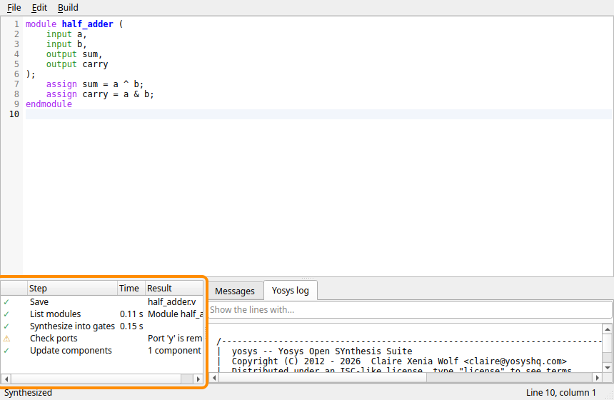
If you made a typing mistake, a step gets a ✗ instead, and the line with the error is underlined. Fix it and press Ctrl+B again. The Verilog editor guide shows what an error looks like.
7. Connect switches and LEDs
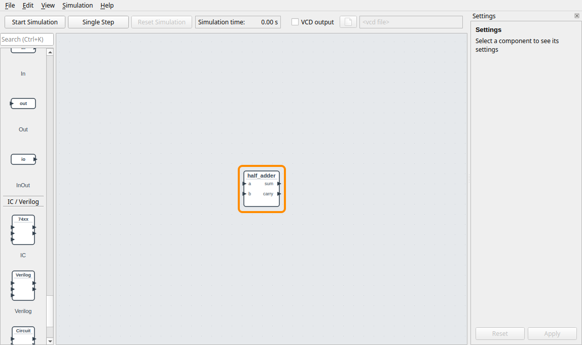
Close the editor with File > Close (Ctrl+W). The component now has the inputs a
and b, and the outputs sum and carry:
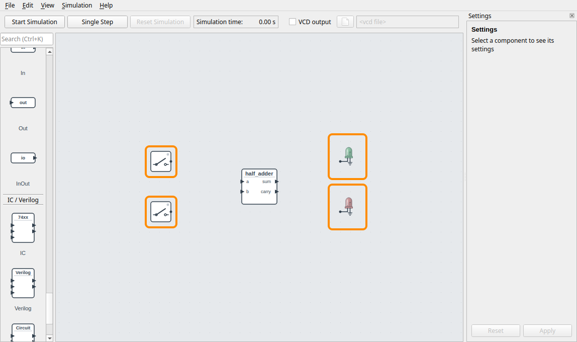
Add the parts to try it with:
- two OnOffSwitch from the Input group, to the left of the component, one above and one below it,
- two LED from the Output group, to the right of it, one above and one below. Choose green for the upper one, the sum, and red for the lower one, the carry.
Connect them as in Your First Circuit: click a port, and then the port to connect it to.
- the upper switch to
a, the lower switch tob, sumto the green LED,carryto the red LED.
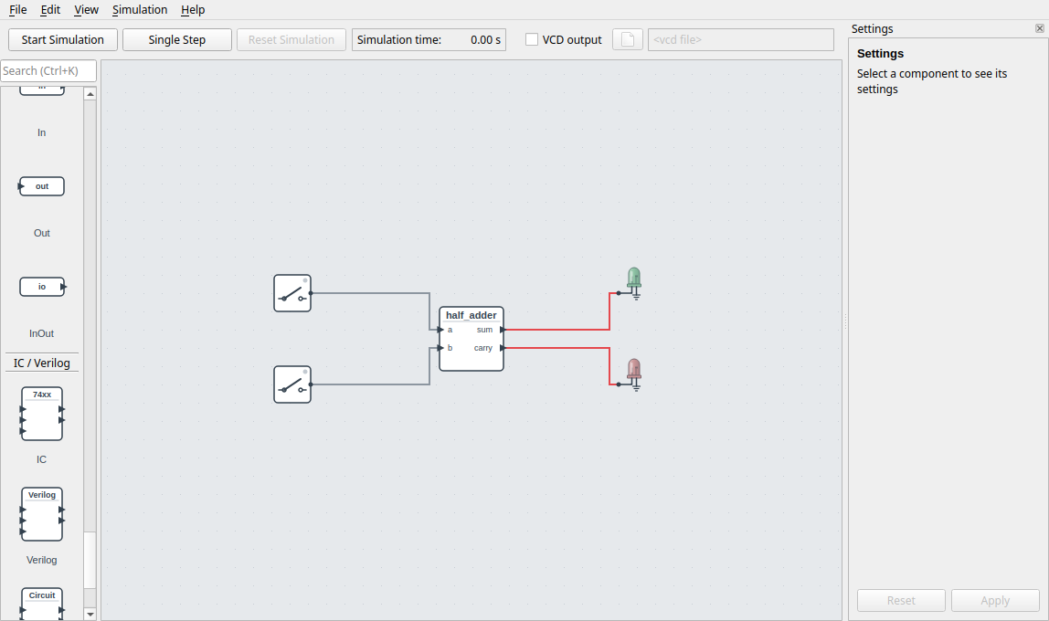
The wires from the outputs are red: the outputs are undefined until the simulation runs.
8. Run it
Click Start Simulation, and turn on the upper switch. One input is 1, so the sum is 1 and the green LED lights:
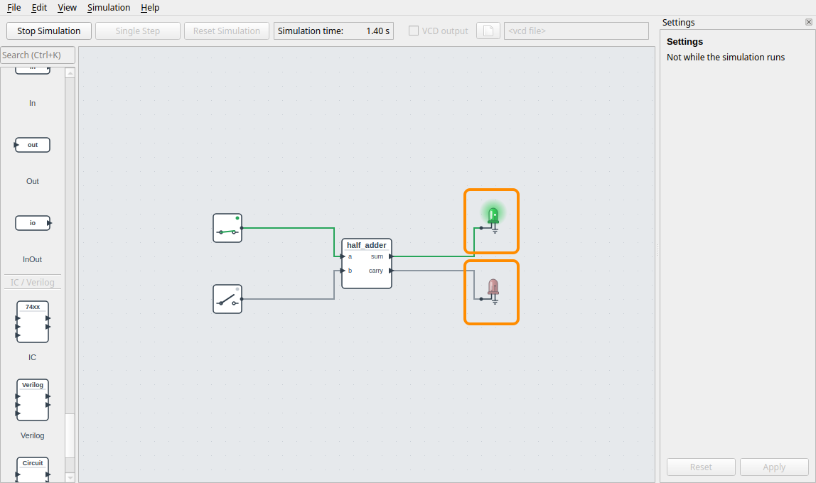
Turn on the lower switch too. 1 + 1 = 2, which is 10 in binary: the carry is 1 and the sum is 0, so the red LED lights and the green one goes off:
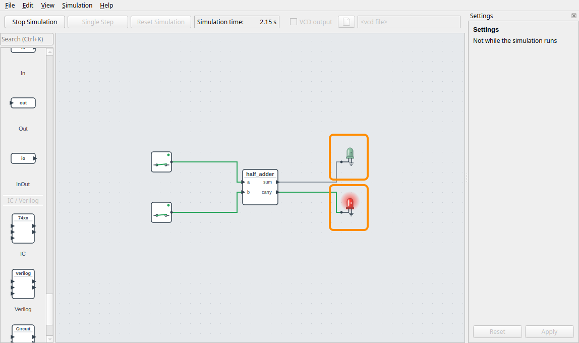
Try all four combinations and compare them with the table in step 5. Then click Stop Simulation.
9. Save the circuit
Choose File > Save (Ctrl + S), and save the circuit in the folder of half_adder.v, for example
as half_adder.circuit. The circuit file refers to the Verilog file, by a path relative
to the circuit, and DigSim synthesizes it again when you load the circuit.
What next
- Change the design: right-click the component and choose Edit Verilog... to open the editor again. Editing a Verilog Component shows more of the editor, with a counter.
- A full adder: add a carry input,
input cin, and add it in:sumisa ^ b ^ cin, andcarryis(a & b) | (cin & (a ^ b)). - Wider designs: ports can be buses, like
input [3:0] x. Connect them to a DIP switch or a hex digit, through Bus2Wires and Wires2Bus. - Verilog from Python: use the same file in a Python circuit or a pytest testbench, see Verilog and Yosys.