Verilog Testbench with pytest
DigSim can be the simulator in a testbench for a Verilog design. Yosys turns the design into a netlist, DigSim simulates it, and the test itself is plain Python, run with pytest. There is no separate simulator to install, and the tests can write a VCD file to look at in a waveform viewer.
This page walks through the testbenches in
examples/pytest_tb:
a 4-bit up/down counter and an 8-bit ALU. Install DigSim and pytest into a virtual
environment first, see Installation.
The design under test
The counter has a clock, an active low reset, and inputs to count up or down
(up_down_counter.v,
shortened):
module up_down_counter(clk, nrst, up, down, value);

   input clk;
   input nrst;
   input up;
   input down;
   output reg [3:0] value;

   always @ (posedge clk, negedge nrst)
     begin
        if (nrst == 0)
          value <= 0;
        else if (up)
          value <= value + 1;
        else if (down)
          value <= value - 1;
     end

endmodule
Loading the design
A pytest fixture creates a circuit with the design as a YosysComponent, the device under
test (DUT). Its ports get the names of the Verilog module's ports, so the counter has
dut.clk, dut.nrst, dut.up, dut.down and dut.value:
import pathlib

import pytest

from digsim.circuit import Circuit
from digsim.circuit.components import YosysComponent
from digsim.synth import Synthesis
from digsim.utils import YosysNetlist


@pytest.fixture(scope="module")
def dut():
    circuit = Circuit(vcd="up_down_counter_test.vcd")
    counter = YosysComponent(circuit)
    verilog = pathlib.Path(__file__).parent / "up_down_counter.v"
    synthesis = Synthesis([str(verilog)], "up_down_counter")
    counter.create_from_netlist(YosysNetlist(**synthesis.synth_to_dict()))
    circuit.init()
    yield DutTester(circuit, counter)
Synthesis runs Yosys on the Verilog files and synth_to_dict() returns the netlist,
see Verilog and Yosys. Naming the top module like this also works for
designs with several modules. For a file with one module,
YosysComponent(circuit, path="up_down_counter.v") synthesizes it in one step.
With scope="module", the design is synthesized once for all tests in the file, and the
tests share the DUT. Each test therefore starts with a reset. Synthesis of a small design
takes a fraction of a second, so a fresh DUT for each test, with the default function
scope, works too.
Driving the inputs
The DUT's inputs aren't driven by other components, so the test sets them directly with
.value, and reads the outputs the same way. After a change, the test runs the circuit
for a while, so that the change goes through the gates of the netlist. A helper class
keeps the tests short:
class DutTester:
    """A helper class to test the up/down counter DUT (Device Under Test)"""

    def __init__(self, circuit, dut):
        self._circuit = circuit
        self._dut = dut
        # Initialize DUT inputs
        self._dut.clk.value = 0
        self._dut.nrst.value = 0
        self._dut.up.value = 0
        self._dut.down.value = 0

    def reset(self):
        """Reset the DUT"""
        self._dut.nrst.value = 0
        self._circuit.run(ms=1)
        self._dut.nrst.value = 1
        self._circuit.run(ms=1)

    def clock(self):
        """Generate a clock cycle"""
        self._dut.clk.value = 1
        self._circuit.run(ms=1)
        self._dut.clk.value = 0
        self._circuit.run(ms=1)

    def up(self, up):
        """Set the 'up' signal"""
        self._dut.up.value = 1 if up else 0
        self._circuit.run(ms=1)

    def value(self):
        """Get the counter value"""
        return self._dut.value.value
A few things to know:
- Give every input a value before the first clock. An input that was never set is
undefined,
"X", and so are the outputs that depend on it. Until the reset, the counter value reads"X"too. - Buses are integers. A 4-bit output reads as a number from 0 to 15, and a bus input takes a number.
- Run long enough. The gates of a netlist have delays of a few nanoseconds, so a design this size settles well within 1 µs. The examples run 1 ms per step, which is more than enough and makes the waveforms easy to read.
Writing the tests
Each test resets the DUT, sets the inputs, clocks it and checks the outputs with
assert:
def test_count_up(dut):
    """Test up counting function"""
    dut.reset()
    assert dut.value() == 0
    dut.up(True)
    dut.down(False)

    for idx in range(1, 16):
        dut.clock()
        assert dut.value() == idx

    # Assert wrap around from 15 to 0
    dut.clock()
    assert dut.value() == 0
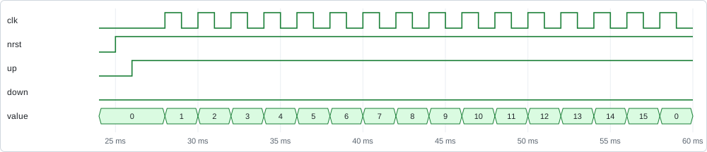
In the waveforms of this test, the reset is followed by up, and each clock cycle counts
one up, from 0 to 15 and around to 0:
The other tests check that the counter doesn't count with neither input set, counts down
and wraps from 0 to 15, counts up when both inputs are set, and resets after counting.
The whole file is
test_up_down_counter_testbench.py.
A design without a clock
The ALU testbench tests a combinational design: an 8-bit ALU with an operation code and
two operands. It has no clock or reset: the test sets the inputs, runs the circuit and
reads the result
(test_alu_testbench.py):
ALU_OP_ADD = 0
ALU_OP_AND = 2


class DutTester:
    """A helper class to test the ALU DUT (Device Under Test)"""

    def __init__(self, circuit, dut):
        self._circuit = circuit
        self._dut = dut
        # Initialize DUT inputs
        self._dut.A.value = 0
        self._dut.B.value = 0
        self._dut.op.value = 0

    def op(self, op):
        """Set the ALU operation"""
        self._dut.op.value = op
        self._circuit.run(ms=1)

    def operands(self, A, B):
        """Set the ALU operands"""
        self._dut.A.value = A
        self._dut.B.value = B
        self._circuit.run(ms=1)

    def result(self):
        """Get the ALU result"""
        return self._dut.O.value

    def alu_op(self, op, A, B):
        """Helper function to execute a full ALU operation"""
        self.op(op)
        self.operands(A, B)
        return self.result()


def test_add(dut):
    """Test the ADD operation"""
    assert dut.alu_op(ALU_OP_ADD, 10, 5) == 15


def test_and(dut):
    """Test the AND operation"""
    assert dut.alu_op(ALU_OP_AND, 0x12, 0xF0) == 0x10
The waveforms of the ALU testbench, in hexadecimal. The helper sets the operation first and the operands 1 ms later, so each new operation first works on the operands of the one before, which gives the short results in between:

For many cases of the same check, @pytest.mark.parametrize gives each case its own test.
Running the tests
From the repository root:
uv run --with pytest pytest -v examples/pytest_tb
examples/pytest_tb/test_alu_testbench.py::test_add PASSED
examples/pytest_tb/test_alu_testbench.py::test_sub PASSED
...
examples/pytest_tb/test_up_down_counter_testbench.py::test_count_up PASSED
examples/pytest_tb/test_up_down_counter_testbench.py::test_count_down PASSED
...
A failing assert shows the expected and the actual value, like any pytest test.
Waveforms
Circuit(vcd="up_down_counter_test.vcd") writes every signal of the design to a VCD file
while the tests run. The tests share the circuit, so the file holds all of them, one after
the other. Open it in GTKWave or a similar viewer to
see what happened, for example when a test fails:
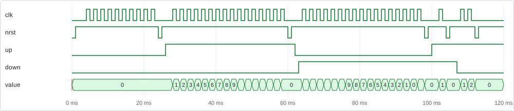
The waveforms show all the counter tests in order: no counting, counting up to 15 and wrapping to 0, counting down, and resets.